
MSV80 wiring diagram
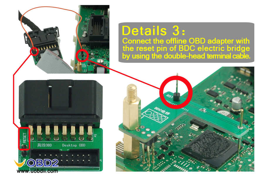
FEM BDC reset wiring diagram
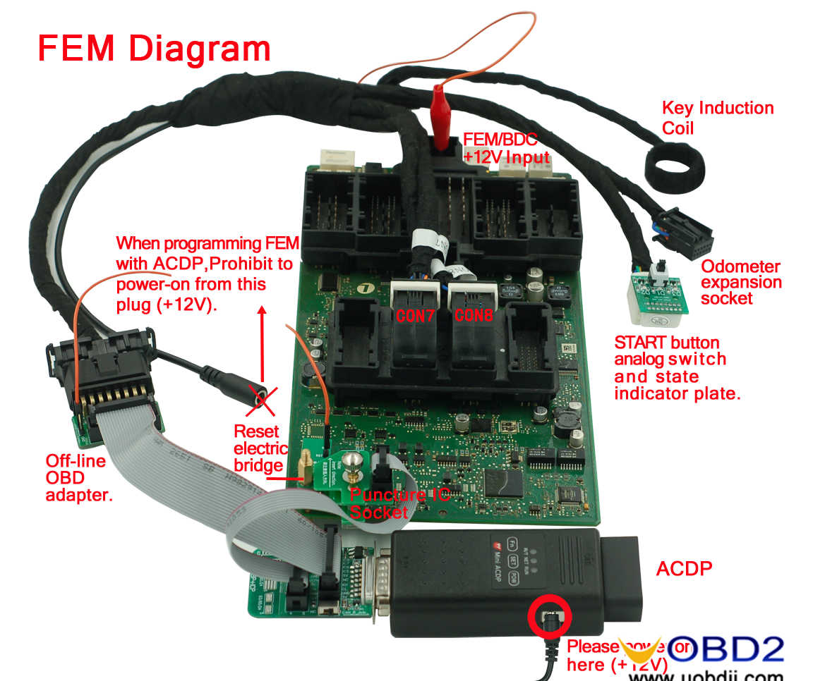
 FEM wiring diagram

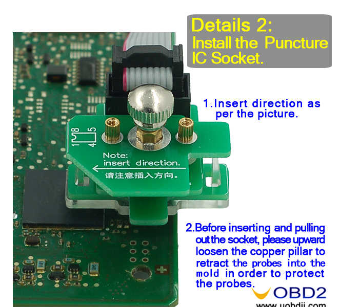
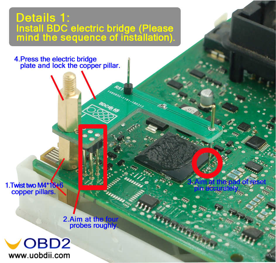
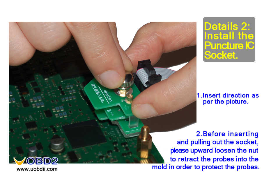
 BDC wiring diagram


 CAS3 OBD wiring diagram

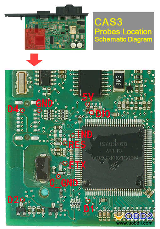
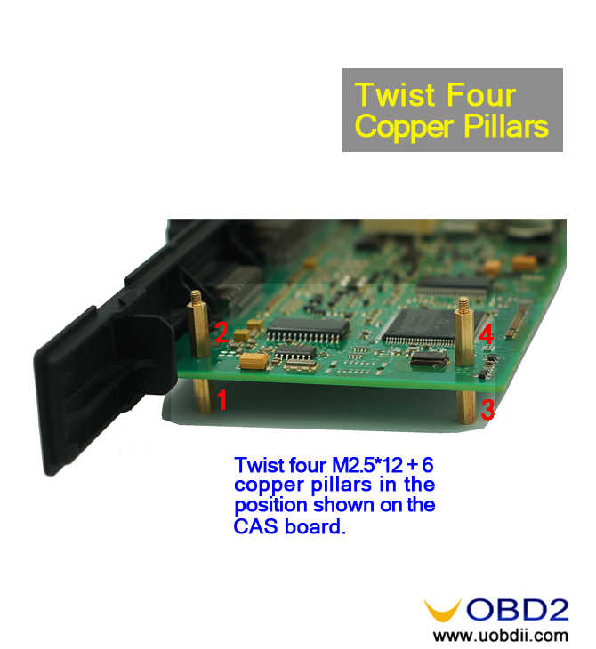
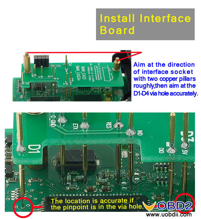
CAS3 wiring diagram

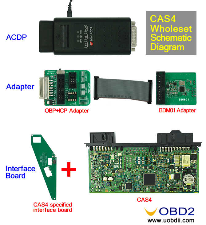
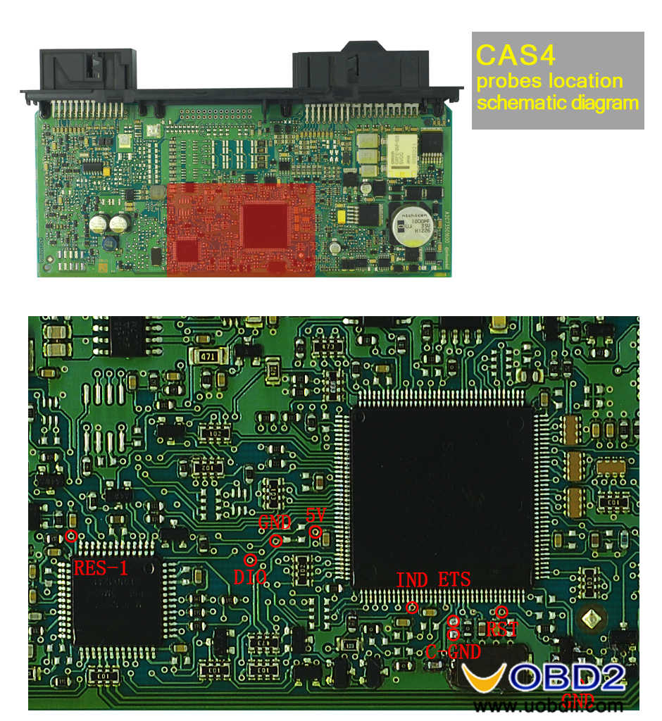
 CAS4 wiring diagram


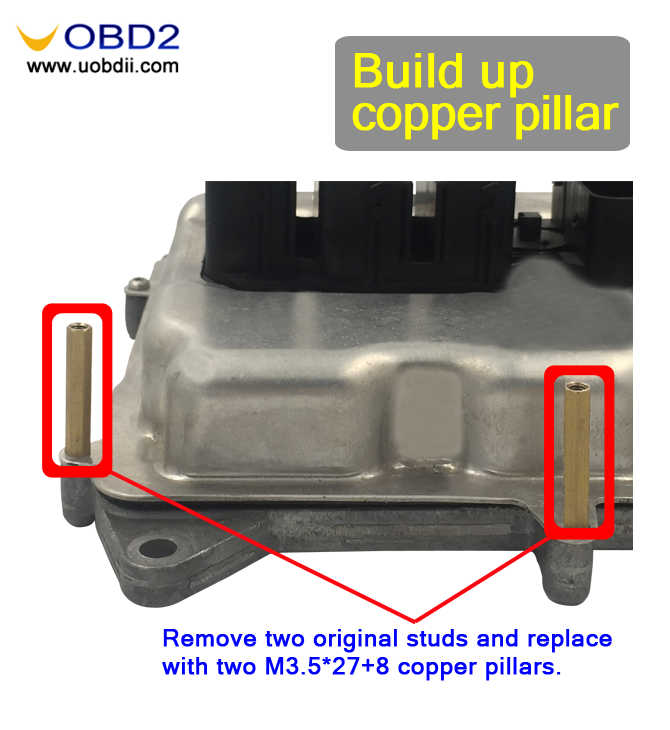
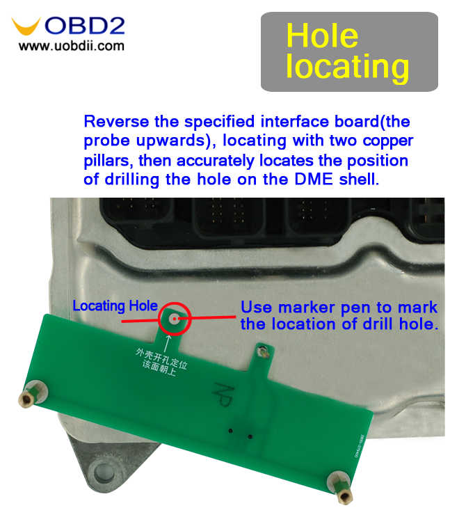
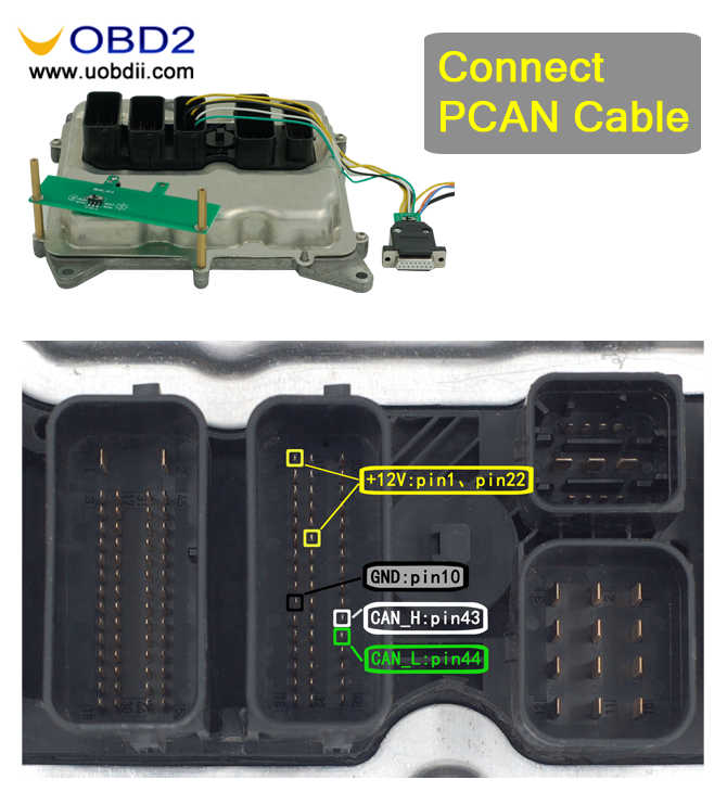
 N20 BOOT wiring diagram


 New IC wiring diagram


 OBP wiring diagram


 VM MMC wiring diagram


 Src:https://www.uobdii.com/wholesale/yanhua-mini-acdp-programming-master.html
No comments:
Post a Comment